
Jesus Chavez Sagarnaga, Director of Structural Engineering, Jenike & Johanson, Inc.
Introduction
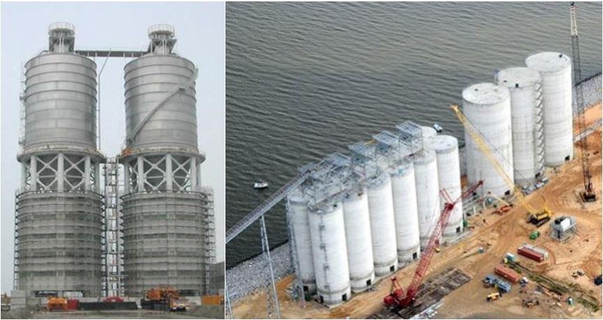
Bin and silo structures (the term “silo” will be used to cover both types of structures in this article) are some of the most critical pieces of equipment in industrial facilities, and they are heavily used all around the world in many industries to store bulk granular solids such as grains, coal, plastic pellets, and mineral ore among many others (see Photo 1). It is vital to ensure both reliable flow and structural integrity when designing such structures. Unfortunately, lack of training in this subject at the undergraduate program level as well as guidance in the literature including standards and codes limit the ability of engineers to take on such a task. Many engineers when faced with the need to analyze and design a structure for storing a bulk solid tend to assume theories that may be better known but inapplicable. For example, the wrong assumption that a flowing bulk material behaves like a flowing liquid is commonly made. For those familiar with bulk solids behavior, it is well known that solid particles can transfer shear stresses between each other and with silo walls even if there is no relative motion between them. Fluids do not exhibit this behavior. The material-induced loads not only have to be in line with the bulk solids behavior but also with the design of the storage structure. Appropriate theories related to shell structures need to be utilized including their failure modes and critical structural details taking into consideration operation and properties of bulk solids.

Photo 1. Metal (left) and concrete (right) silos
In the following paragraphs, topics related to the design of silo structures will be discussed. These topics include behavior of stored bulk solids, material-induced loads, and structural design of shells. Bulk solids flowability properties are crucial for reliably designing silos from their functionality point of view. The equipment to obtain many of these properties has been described elsewhere 1 as well as the applicability of those properties for reliable designs 2 , so these topics will not be covered here.
Behavior of Bulk Solids in Silos
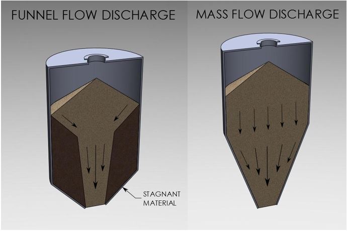
The behavior of bulk solids in silos is critical for their design since the flow patterns developed are linked to different loading scenarios. There are two primary flow patterns that a silo can develop during discharge: funnel flow and mass flow (see Figure 1).

Figure 1. Funnel and mass flow patterns
In funnel flow, an active flow channel forms above the hopper outlet, with stagnant material at the periphery. When the cohesive strength of the stored material is sufficiently large, the stagnant material does not slide into the flow channel, which results in the formation of a stable empty vertical or near vertical channel commonly called a rathole.
In mass flow, all of the material is in motion whenever any is withdrawn from the hopper section. Material from the center as well as the periphery moves toward the outlet, though not necessarily at the same velocity. A proven, practical approach to achieving mass flow is outlined in Dr. Andrew Jenike’s work presented in Bulletin 123 2 .
A third type of flow pattern, called expanded flow, can develop when a mass flow hopper (or hoppers) is placed beneath a funnel flow hopper. Particularly for large diameter silos, the major advantage of an expanded flow discharge pattern is the savings in headroom, as compared to a complete mass flow design.
Eccentric discharge can occur with a mass flow or funnel flow pattern, but it is more common with funnel flow. In either case the flow channel formation is not concentric with the cylindrical section of the silo. In the worst-case scenario, the flow channel intersects the cylinder wall and runs parallel to it until the top, free surface is reached.
Material-induced Loads in Silos
Initial fill loads develop when an empty silo is filled with the bulk material without any withdrawal of material taking place. Silos discharging in funnel flow where the flow channel never intersects the cylinder walls are subjected to initial fill loads only, regardless of whether the silo is being discharged or not.
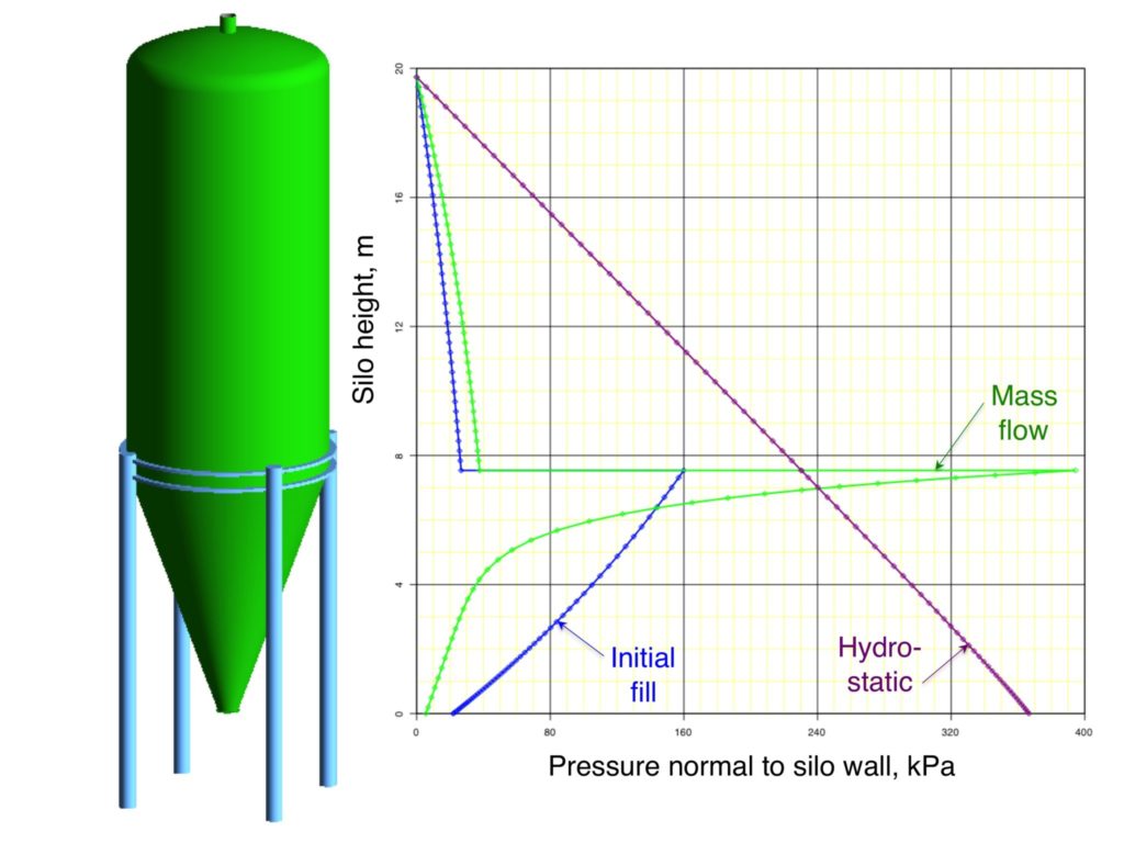
Flow loads develop as soon as a silo starts to discharge. Once flow loads develop, flow can be stopped and then restarted without having any appreciable effect on the loads exerted on the silo walls. Silos discharging in mass flow exert flow loads on the silo structure while those discharging in an expanded flow pattern have a combination of initial fill and flow loads. Figure 2 shows typical curves for pressures acting normal (i.e., perpendicular) to a silo’s walls for initial fill and flow loads conditions in a mass flow silo with a circular cylinder and a conical hopper configuration. Concentric fill and discharge have been assumed. The hydrostatic condition has also been plotted in the graph for comparison.

Figure 2. Initial and flow loads in silos
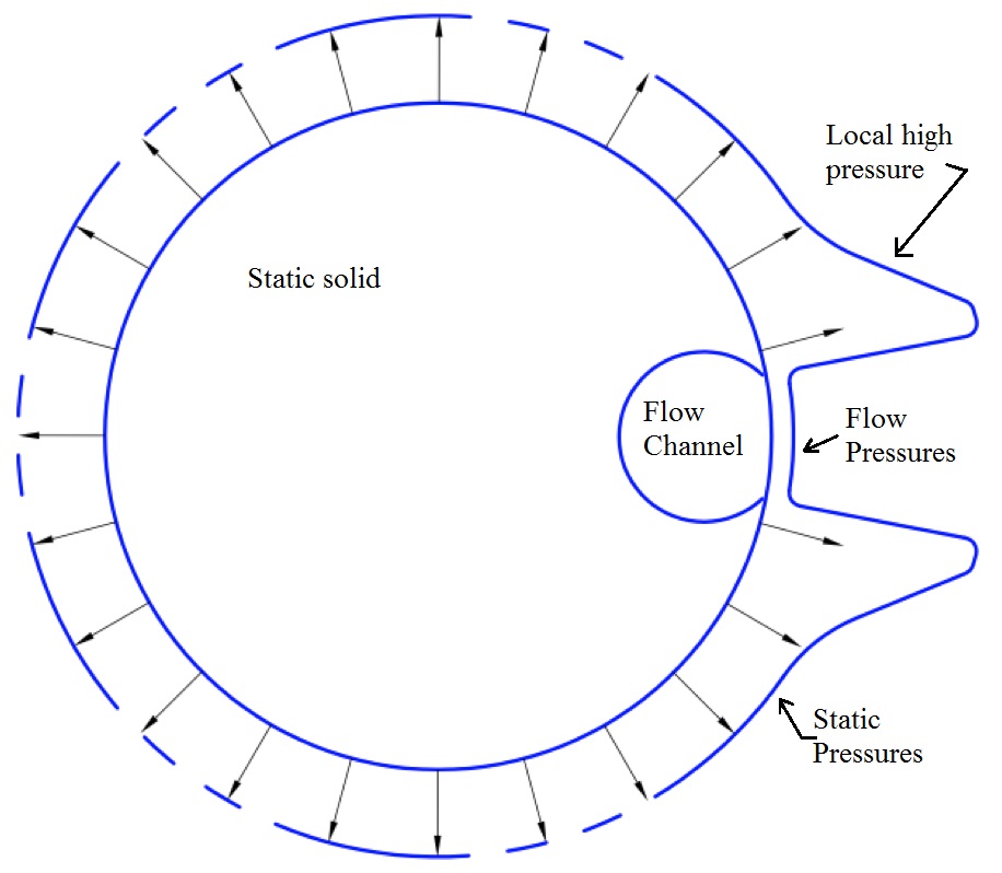
Eccentric discharge from a silo results in asymmetric pressures developing. If the resulting flow channel intersects the silo wall, non-uniform pressures will develop around the circumference of the silo leading to circumferential bending and axial compression on the cylinder shell. A schematic representation of this pressure profile in a cross section of a cylinder is shown in Figure 3. Note that the pressure normal to the cylinder walls in the flow channel is much less than the normal pressure in the surrounding bulk material. Furthermore, there exists a localized region of high pressure at each edge of the flow channel 3 .

Figure 3. Non-uniform pressures caused by eccentric discharge
Structural Analysis and Design of Shells
Metal silos with circular geometry are efficient structures if internal pressures, due to the stored bulk solid, are applied uniformly. This occurs if the silo is filled and discharged concentrically. The shell stressed in this way is subjected to tension in the circumferential direction, thus being an extremely efficient structural system. Even though the stored material exerts frictional forces -- which produce axial compression on silo cylinders -- the material exerts pressures that act normal to the walls, which diminish the effects of wall imperfections. This is the reason why metal silos can store large material quantities with a relatively light structure.
The ability of a vertical metal cylinder to resist hoop tension depends on the tensile strength and thickness of the cylinder wall, while its ability to resist vertical compressive stresses depends on the stability of the walls (i.e., the ability to resist buckling). Typically, for metal silos, buckling strength is more critical than their ability to resist hoop tension. It is important to note that thin shells are sensitive to surface imperfections; therefore, they usually buckle at stresses much smaller than the theoretical value when axially compressed. Cylindrical shells fabricated in structural fabrication shops often have low local-buckling strengths since a low level of surface imperfections is difficult to achieve.
If concrete silos are filled and discharged concentrically, they will also experience uniform pressures around their circumference. Ability to resist tension is not one of concrete’s virtues, so concrete has to be reinforced with steel bars to provide resistance to tensile stresses. Concrete silos with a single layer of horizontal reinforcement are capable of resisting hoop tension in an efficient manner.
Concrete silos rarely fail due to axial compression as the cylinder walls are relatively thick, and concrete behaves much better under compression than tension. However, tension and bending moments that develop, for example, by asymmetric discharge, can cause severe damage to the walls of concrete silos by developing dangerous cracks and, in other cases, concrete spalling. Therefore, the walls must have design strengths at all sections at least equal to the required strength calculated for the factored forces, moments, and shears in accordance with the American Concrete Institute’s (ACI) various codes and standards.
Commonly Used Standards/Codes
The most commonly used Standards/Codes for silo design cover in a limited way the critical and intimate relationship between structural design, material-induced loading pattern, and behavior of the bulk solids developed during storage and discharge of silos. In some cases, these relationships are not covered at all. The most common Standards/Codes are presented in the following paragraphs.
Conclusions
It is the responsibility of the engineer in charge of designing a silo to ensure it is based on sound, complete knowledge of the materials being handled, that the design is competent, and that it covers all foreseeable loading combinations as well as their effects in the structural system. However, without appropriate training and codes/standards in the engineering field on how to design a silo structure, this is a daunting task which can easily lead to silo failures.
References